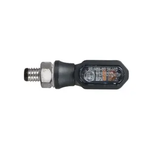
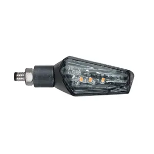
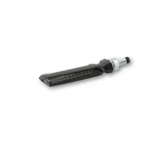
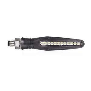
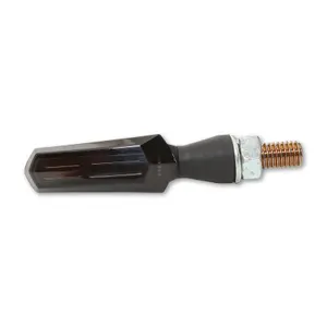
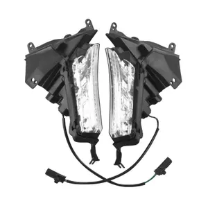
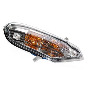
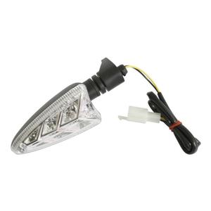
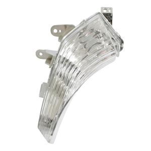
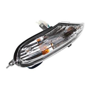
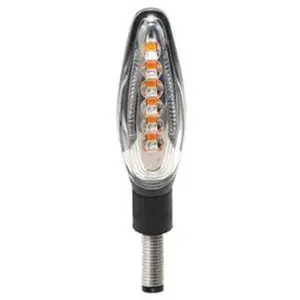
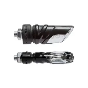
Motorcycle turn signals
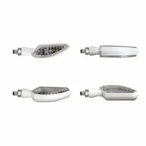
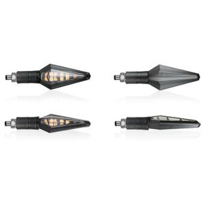
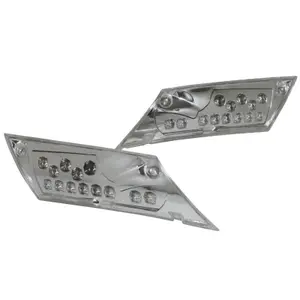
Personalise your motorbike with your own image, find our LED and bulb indicators with an exclusive look
The installation of resistors when changing indicators will depend on 2 parameters:
- The power of the original indicator
- The power of the adaptable indicator to be fitted
The difference in power will be compensated by the resistor so that the new indicator works optimally.
Ex: Let's take an indicator with an original bulb developing 21W and a LIGHTER sequential LED indicator ref IN1126.
The difference in power to be made up is 21W - 2.4W = 18.6W per indicator.
With the engine running, the alternator delivers a voltage of approximately 13.5V.
Here we are looking for the resistance to compensate for the power of 18.6W
The formula used according to Ohm's law is R (resistance) = V (voltage)²/P (power).
This gives us R=V²/P=13.5²/18.6=9.80 Ω
So it will be enough to mount a 10 Ω resistor (ref IN820) on each flasher to have the correct operation.


